Axes of rotation standard
When building high precision piezo stages and systems, measuring the accuracy is a crucial step to verify that our products meet the specifications that our customers demand.
On this page, we discuss the terminology and various tests performed in order to specify the axis-of-rotation error motion of our piezo rotary stages before we deliver a system to our customer.
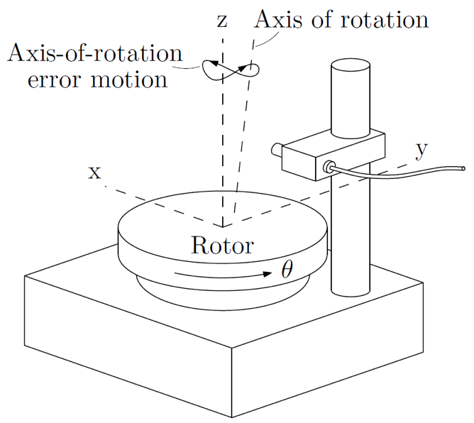
A rotary stage, consisting of a stator and a rotor, ideally has one degree of freedom, i.e. a rotation about the z-axis. However, as perfect rotary stages do not exist, any motion in the remaining five degrees of freedom is referred to as an axis-of- rotation error motion or simply error motion.
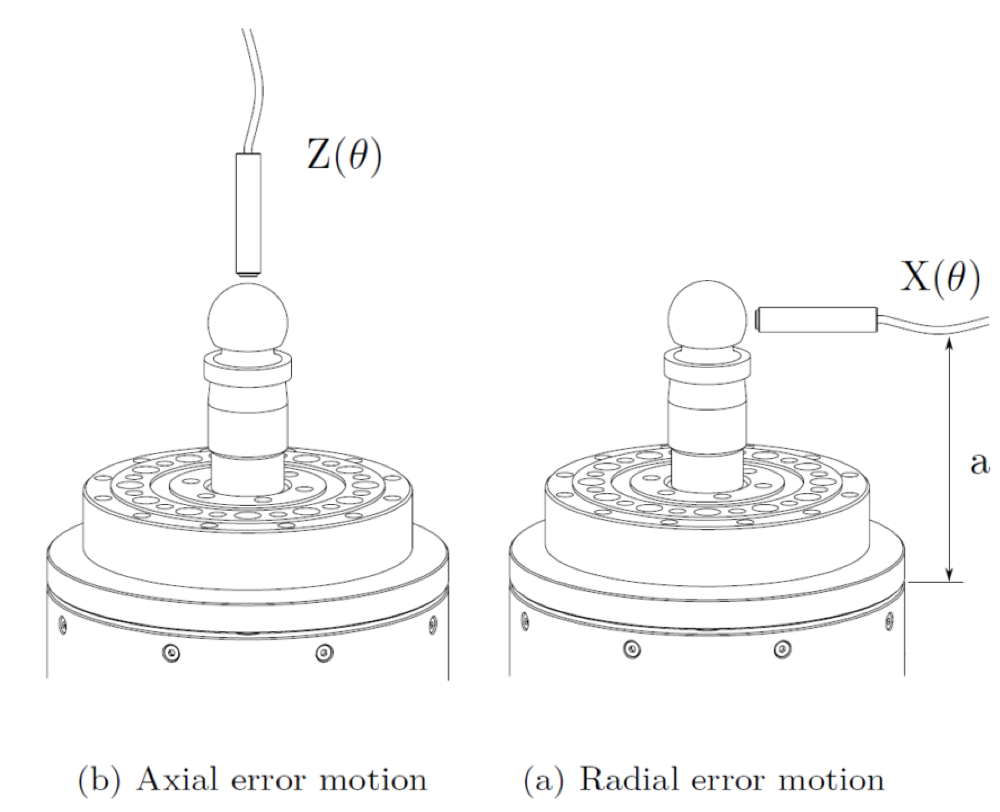
The error motion of a rotary stage is usually characterised with a displacement indicator (capacitive sensor) targeting a lapped artefact which is mounted to the rotor of the stage. The error motion of a stage is fully characterised by five error motion components, namely:
Radial error motion (x(θ), y(θ)): defined as the error motion perpendicular to the axis of rotation measured at an arbitrary axial location ‘a’. The axial location must always be specified since tilt of the rotor influences the radial error motion.
Axial error motion (z(θ)): defined as the error motion collinear with the axis of rotation.
Tilt error motion (α(θ), β(θ)): defined as the rotation of the rotor about the x- and y-axis. This error motion can be derived from two radial error motion measurements made at different axial locations ‘a’.
Synchronous versus asynchronous error motion
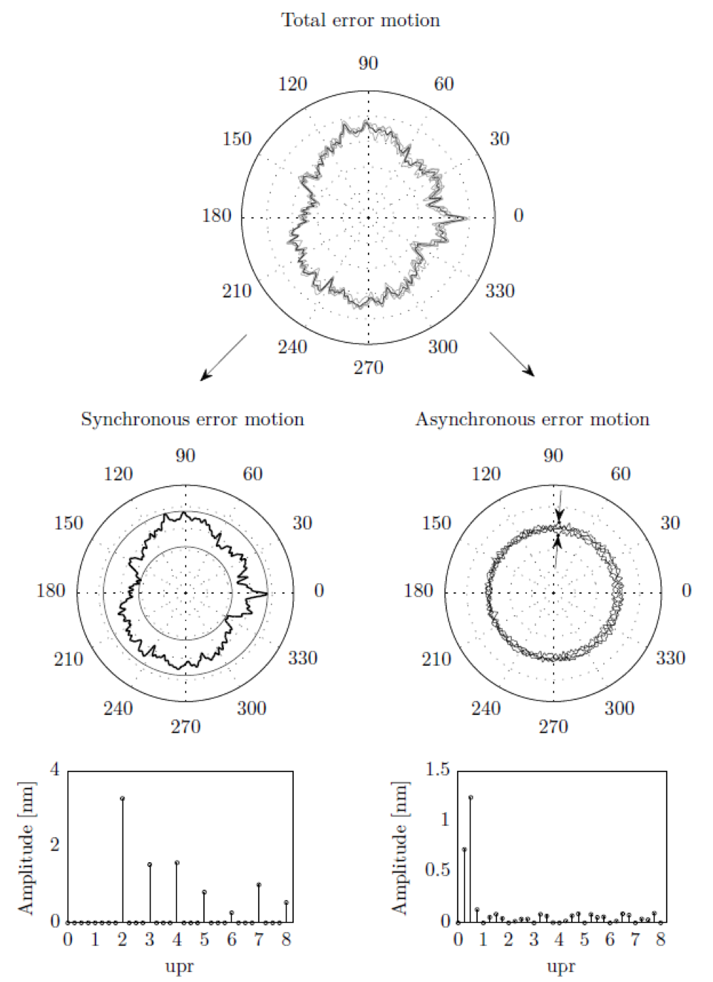
The total error motion of the stage consists of a synchronous and asynchronous component:
The synchronous error motion is the portion of the total error motion that repeats from revolution to revolution. It can be obtained by calculating the average error at each measured spindle angle θ over several revolutions. In mathematical terms, this is defined as the error motion which is composed of the integer multiples of the fundamental frequency.
The remaining content of the total error motion is the asynchronous error motion. It is composed of the non-integer multiples of the fundamental frequency. In other words, the portion of the total error motion that does not repeat from revolution to revolution. It reflects some unknown combination of the stage error motion, environmental disturbances, structural vibrations and noise during measurement.
Error motion value
The error motion value of the total, synchronous and asynchronous error motion can easily be determined when graphed on a polar plot. Namely as the difference between the radii of two concentric circles that enclose the corresponding error motion. The least squares circle (LSC) centre is the preferred polar plot centre for error motion assessments.
The synchronous error motion value is determined by subtracting the radii of the minimum circumscribed circle and maximal inscribed circle of the synchronous data with a common LSC centre. The asynchronous error motion value, in turn, is obtained from the largest peak-to-valley range of the asynchronous data by looking at each angular position individually. The maximum band of the asynchronous error in is indicated by the two arrows in the figure above.