All you need to know about mass compensation
Reading time: 5 min
As you can read on our website, ultrasonic piezo stages are good at positioning objects very precisely at a high speed. That makes them suitable for scientific research and specific industrial and medical applications. The way piezo stages function works well for movements in the horizontal plane (XY), but lifting objects in the vertical plane can be challenging. In this overview we will discuss the different ways this hurdle can be overcome.
Why is vertical movement more difficult?
We also published a detailed description on how the different kinds of piezo motors work. They all have their specifics, but all piezo motor technologies have one thing in common: a ceramic component pushes against a ceramic strip to induce a motion and then goes back to its initial position to repeat the movement and give a new push. This mechanism creates two challenges when moving against gravity:
1. The piezo motor needs to push harder than in the horizontal plane to move the payload, as it has to “lift” the entire payload weight
2. When the piezo motor returns to its starting position, the object should not “fall” back down
Instead of changing the basic principles of the piezo motor mechanism, people have looked for ways to make the piezo motor think it is still moving in the horizontal direction, where the two challenges mentioned above don’t exist. There are two basic approaches: increasing the force of the piezo motor considerably or compensating the weight of the payload.
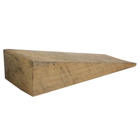
Wedge
When the force of the piezo motor is increased the problems of heavy payloads decrease or disappear. Increasing the force can be done with a wedge system, which amplifies the force of the motor at the expense of decreasing travel range. These kinds of mechanisms cannot just be added to an existing piezo stage, but need to be part of the structural design. Most vertical lifting piezo stages with a travel range of more than 2 mm are based on this principle.
When a piezo motor pushes a wedge underneath the payload, large lifting forces can be generated. The resulting force is dependent on the angle of the wedge. The smaller the angle of the wedge, the more vertical force that can be generated. But on the other hand, when a very narrow wedge is being used, there isn’t much vertical net travel left. This can be countered by using a long wedge, but then the challenge becomes the footprint of the stage. In confined spaces like vacuum chambers or beam manipulation setups, this can be an issue. With most piezo lifting stages with wedge systems that you can find on the market, travel ranges of 5 mm up to 15 mm can be achieved.
Magnetic mass compensation
Wedges are great for travelling up to 15 mm, but what do you do when you want to lift an object or a research sample higher than that? In that case, we have to fall back on the regular linear stages in our portfolio, which have travel ranges up to 110 mm. But again, measures need to be taken to avoid the two problems mentioned in the introduction. Eliminating the forces caused by gravity will give the piezo stages the impression that they are operating horizontally. This is called mass compensation.
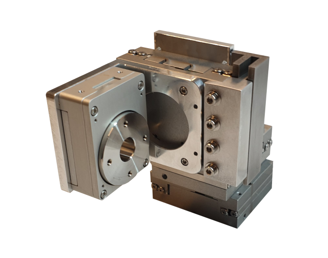
The first mechanism that is being used is a magnet that neutralizes the weight of the payload. When this is done correctly the situation for the piezo stage is the same as with a horizontal movement: Only inertia needs to be overcome but not the entire weight of the load. And there is no risk of the “falling back” as explained earlier.
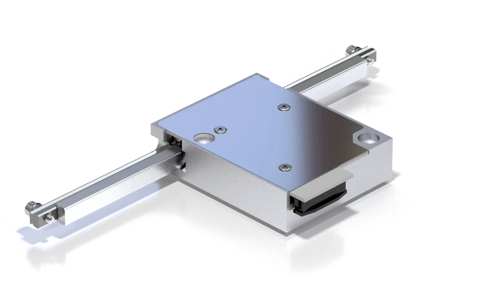
A magnetic mass compensation is constructed following a principle called a “reluctance actuator”. In theory, this can be done with permanent magnets and electromagnets, but in practice, only permanent magnets are being used. Without going too much into technical detail, the concept is to slide a permanent magnet between two iron rails that have a varying distance between them. This generates a constant lifting force on the magnet. The force is dependent on the magnet and the iron plates. This means that the payload shouldn’t vary too much as the magnet is selected for a specific mass to compensate.
A magnetic mass compensation can be easily mounted on the side of an existing piezo stage. The length of the compensation is determined by the length of the magnet and the rail. Typically, the length of the rail is about twice the travel range you want to achieve. So, for long travel ranges you can end up with magnets and rails that are quite high.
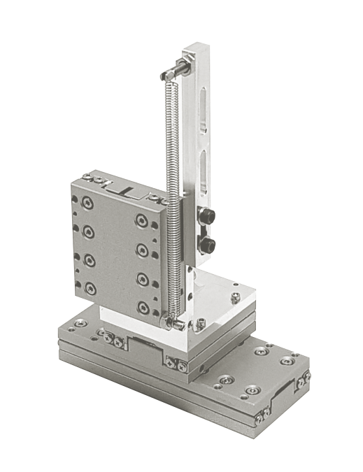
Mechanical spring mass compensation
Magnetic mass compensation works well, but as you might have guessed, it generates a magnetic field. For some applications, this is not acceptable. Using a constant force spring can be a solution when no magnets are allowed. There are two types of springs that are relevant for this concept.
1. A long linear spring
A classic tension spring doesn’t have a constant force, so at first glance, it isn’t suitable for mass compensation (where you want a constant compensation force). But if you take a long spring and you use it in a region where it is not too tense yet, the force is reasonably constant. It is not perfect, but the piezo motor can overcome this fluctuation.
Mass compensation with a linear spring works, but you need sufficient height to be able to use the spring in the spring region where the spring force is constant. The concept can be added to any stage as long as a sufficient working height is available. An advantage of this idea is that, in case of varying payloads, different springs can be mounted. This makes this concept more flexible than magnetic mass compensation.

2. A circular constant force spring
You probably know this principle from a rolling meter. A circular constant force spring is a long band of metal (sometimes slightly bent) that is rolled up. When pulled upon, it generates a constant pulling force. Some manufacturers of piezo stages have integrated this concept into some of their vertical stages. It is more complex to make it work, and although you don’t need the extra height that a linear spring needs, you still need to position the spring above the stage to lift it. This could be countered by using rollers that guide the spring back down at the risk of influencing the elastic behaviour of the spring.
Counterweights
The concept of a counterweight is simple: you tie a weight to a rope, it goes up to a roller and comes back down to the payload. When chosen correctly, the weight of the load can be compensated perfectly. The big advantage of a counterweight, compared to the previous principles, is that the force is perfectly constant. So why is this not the ideal solution?
First, the dummy weight can start swinging when the vertical stage is mounted onto an XY platform, so measures should be taken to avoid this. Secondly, the imperfections of the materials can cause issues. Most piezo stages are used in extremely demanding settings, with positioning resolutions of less than 100 nm and sometimes even below 1 nm. Any imperfection in the roller or the material of “the rope” can create issues with the positioning precision of the stage. Nevertheless, when executed well, the counterweight concept is useful and reliable. It also allows for varying payloads by adding or removing some dummy weights.