The definitive guide to ultrasonic piezo technology
Reading time: 5 min
A little bit of history
It all started with the discovery of the pyro-electric effect in the 18th century. Scientists discovered that when certain materials were heated, they generated an electric potential. About a century later, although the suspicion of the existence was older, by the end of the 19th century the piezo-electric effect was discovered by Pierre Curie.
In this case, the application of pressure to certain materials generated an electric potential. The breakthrough was a consequence of the rapid progressing insight in crystal structures, or crystal physics. And it was only a couple of years later that the inverse effect was confirmed mathematically: When you put an electric potential on the same crystal, a physical expansion can be noted. This is known as the converse piezoelectric effect and still is the basis of the current piezo motors.

Do all crystals qualify?
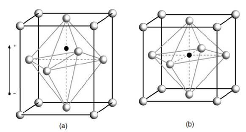
The essence of a piezoceramic material is that it contains electric dipoles that can be arranged into a permanent dipole orientation, even after removal of the polarisation field. This field is a strong DC field that aligns the present dipoles all in the same direction, giving the structure as a whole a dipole orientation. Many materials have a certain level of piezo ceramic effect, but very often the effect is too weak to be useful or the material itself isn’t strong enough to withstand the physical forces generated by the piezo effect. Or to put it differently: they break because of mechanical expansion. This phenomenon is often seen in single crystal materials. Much better results are obtained with polycrystalline ceramic materials. Finally many monocrystalline materials are very sensitive to moisture, rendering them useless in many day to day applications.
The most commonly used material for piezo ceramics is lead zirconate titanate, also known as PZT. Typically for a piezo material is the combination of a ceramic with a metal. Why? Ceramics have piezo properties, but typically are very brittle. This limits the amount of expansion a ceramic crystal can undergo without breaking. By adding one or more metals to the crystal structure, the combination becomes mere elastic, allowing for a larger expansion, which on its turn is ideally for piezo motors, where the degree of expansion is directly related to the movement of the motor within one expansion cycle. In other words: a less brittle material creates a motor with a greater stroke. The moisture sensitivity is also much better, making these ceramics ideal for a wide range of applications.
How are they made?
All the components are mixed together in a very fine powder. Typically an organic material is added in this phase to get a better binding of the materials, which is later removed again by heating the mixture. Another heating is then applied while the powder is still in the crucible to give it its definite shape. This shape can be a flat tile, a cylinder or basically any other shape that can be made this way.
Once the shape is given, the material needs to be polarised. The polarisation is done in a heated oil bath and a DC voltage is applied over the piezoceramic element during a period, ranging from a couple of minutes to several hours. The elements are then taken out of the oil bath and let to cool down, resulting in a permanent polarised structure in the material.

The technical mechanism of the piezoelectric effect
In the previous chapter we explained that a piezo ceramic material contains permanent electric dipoles that are all oriented in the same direction. Now you will see why this is useful. When we apply an electrical potential (a voltage) between the two sides of the ceramic material, the electric field will start pushing the positive and the negative charged crystals away from each other. This causes an expansion of the material. This expansion is extremely small, typically in the order of magnitude of a nanometer (one millionth of a millimeter) to a micrometer (one thousandth of a millimeter). So you will need to do a lot of expansions, combined with a mechanism that translates this expansion into a harvestable motion, to get to a real piezo motor.
But there is a huge advantage: the expansion (and the contraction when the voltage is removed) is extremely fast, so you can do a lot of expansions per second. Most piezo motors are doing somewhere between 10kHz and 200kHz (200.000 expansions/contractions per second). Another useful aspect is that the expansion of the piezoceramic material is directly proportional to the voltage that is applied. This is a useful property but it has its limitations. First of all there is the limit on the expansion a material can take before breaking, but there is also a practical limitation. Many piezo motors are used in products that are being handled and touched by people. The higher the voltage, the more careful people need to be to avoid getting a shock if they by accident would touch the ceramic connections. In traditional piezo systems voltages up to 500V are applied, while in ultrasonic piezo much lower voltages are being used (24V - 48V) as the resonant effect has a comparable impact as a higher voltage. For this reason ultrasonic systems are considered safer.
The most basic actuator, the piezo stack
As explained in the introduction, a physical expansion is generated in certain crystalic materials when an electrical potential is applied. This expansion is directly proportional to the voltage that is applied. Obviously there is a limit to this: At a certain point the voltage becomes so high that the crystal breaks. The converse piezoelectric effect results in very small changes in the width of the crystal. That makes it a two edged sword: It’s not usable for displacements larger than a µm, but you gain extreme control over very small distances. This makes piezo crystals very useful for the positioning of objects in the sub-µm world. Think about scientific research where mirrors or lenses need to be placed at a very specific position. Or think about wafer inspection machines, electron microscopes or even medical devices.
To tackle the problem of the limited displacement, very early on the idea emerged to stack multiple piezoelectric crystals, each with a manageable voltage that did not threaten to damage the crystal structure. This is what is called a piezo stack. It is a stack of individually driven crystals that, combined, can give expansions of several µm. Not great, but we’re getting somewhere.
Another strong point of a piezo stack is the forces it can generate. A small stack can easily generate 20N and more. Larger stacks can be used to position very heavy objects in a very precise manner, all be at without a lot of travel range.
We now know the basic principles of the converse piezoelectric effect, but how can we use the advantage of this phenomenon to achieve larger displacements? Several ideas have been put to the test, but only a few survived. Let’s have a look at the most important ones.

The stick-slip motor
The idea of the stick slip motor is simple: You put a piezo stack sideways against a ceramic strip on the slider. In one direction you move slowly, creating a “slip” between the crystal and the slider, but in the other direction you move more slowly, creating a “stick” between the two and as a consequence the slider moves together with the piezo element. It’s clear that in such a movement you have only travelled the same length as the expansion of the crystal, so you need to repeat this movement many thousands of times to travel some length. Fortunately, technically it is perfectly possible to alternate the drive signal in the KHz range.
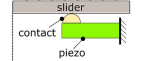
What is the disadvantage? Even with the high frequency of the signal, the slider still moves very slowly. Speeds up to 5 mm/s are possible, but faster is difficult. For some applications this slow speed is an issue. But the biggest disadvantage is the lifetime. The constant slipping of the piezo motor against the ceramic strip on the slider not only generates a disturbing noise but also causes lots of wear on the contact point. Imagine grinding a very small globe thousands of times per second for weeks at a time. Efforts were made to increase the travel per stroke by ramping up the voltage applied to the motor but for safety regulations often only 48V or even 24V is allowed, limiting the effect of this solution.
The ultrasonic piezo motor
In the seventies some Russian scientists came with the concept of using resonance to solve the problems with the traditional stick-slip piezo motors. The idea was simple, let's try to expand and contract the piezo crystal at its own-frequency, in order to make it resonate and expand more, with the same energy. There are two types of ultrasonic piezo motors: the standing wave and travelling wave ultrasonic piezo motor.
In a travelling wave motor, the contact point(s) shift(s) along the motion direction, constantly pushing the slider forward. Typically this is used in expensive camera lenses. The concept is a ring-shaped piezoceramic material, in which a wave is generated by the piezo-effects described above. This wave travels around the ring and a contact point that touches the ring “floats” on the waves and gets a net motion in a direction, opposite to the travelling wave. This principle is hard to apply on a linear motion but very suitable for rotations. The reason is that it is very hard to generate a travelling wave on one end of a linear piece of ceramic and to dampen it away at the other end. In a ring you can just let the wave travel around, again and again. This technology is interesting for cameras because there is a large ring with a big aperture. For other applications it is less useful and the concept only allows for slow speeds. Although the travelling wave piezo motors achieve high forces, they are prone to wear and have a limited lifetime.

The standing wave motor, on the contrary, has one (or a few) defined contact point(s). These contact points vibrate in an elliptical trajectory against a slider, resulting in a net displacement.
In case of the standing wave type, the motion of the contact point is enhanced because the oscillation frequency coincides with two resonance frequencies of the motor structure. Figure 3 shows an example of the resonance modes of an ultrasonic piezo motor, which was developed by Xeryon’s founders at the university of Leuven (KUL) in Belgium. In the first resonance mode, the contact point moves in the tangential direction, i.e. the direction of motion (see Figure 3 on the left). This mode is sometimes referred to as the ‘bending mode’. In the second resonance mode, called the ‘normal mode’, the contact vibrates perpendicularly to the direction of motion (Figure 3 on the right).

Figure 3: Resonance modes of an ultrasonic standing wave piezo motor, developed at KULeuven (Santoso, 2014):
bending mode (left) and normal mode (right)
By carefully selecting the electrical drive signals of the piezo motor, both modes are excited simultaneously, with a phase difference of plus or minus 90 degrees. This leads to an elliptical vibration of the contact point, as shown in Figure 4. Next to the phase difference, the motion trajectory of the contact point can also be controlled by the amplitude or frequency of the drive signals.

Figure 4: Elliptical vibration of the contact point of an ultrasonic piezo motor.
Characteristics of a standing wave ultrasonic piezo motor:
The elliptical trajectory of the contact point can be shaped in such a way, as to have a very small horizontal amplitude, resulting in a small horizontal contribution of motion. This leads to a very fine positioning resolution, without the need for an additional quasi-static scanning mode (which is typically used in stick-slip piezo motors to achieve nanometer resolution). The advantage is that an ultrasonic piezo motor has zero drift after positioning and achieves a good bi-directional position repeatability.
Furthermore, the control strategy of shaping the elliptical trajectory makes it possible to follow a low but constant scanning speed of the slider. The term ‘ultrasonic’ means that the frequency of oscillation lies outside of the audible frequency range for humans. This explains why these motors operate noiselessly, which is a strong advantage when operators work in the vicinity of the system, such as an optical microscope. Additionally, because of the high frequency of operation, one can achieve very high motion speeds of 1000 mm/s and more with an ultrasonic piezo motor. The low power consumption and thus low heat generation of this type of motor is explained by its operation at resonance, which is energetically more favorable than quasi-static operation. This is important in handheld devices and systems which need to be thermally stable, such as vacuum setups or measurement devices.
Finally, these motors can be used to cover long distances and a long lifetime, when used under proper working conditions. This is explained by the lower impact between the contact point and slider, as compared to stick-slip piezo motors.